Previous Chapter:What is Audio Special Purpose ICs and its function?
Next Chapter:What are Data Acquisition ICs?
What Are Clock ICs and How Do They Work in Electronic devices?
Post Date:2024-05-12,Skyworks Solutions Inc.
What Are Clock ICs and How Do They Work in Electronic devices?
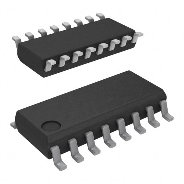
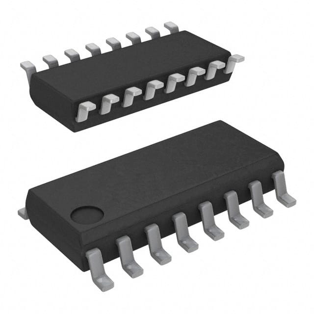
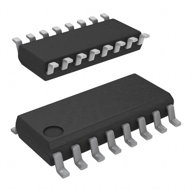
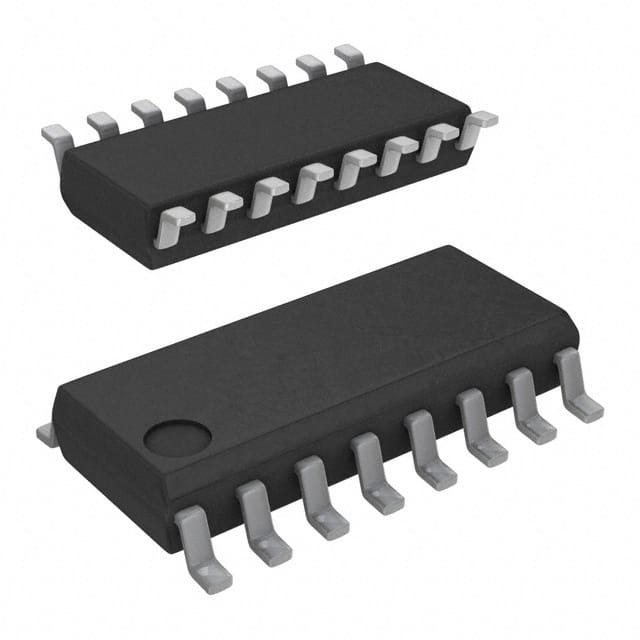
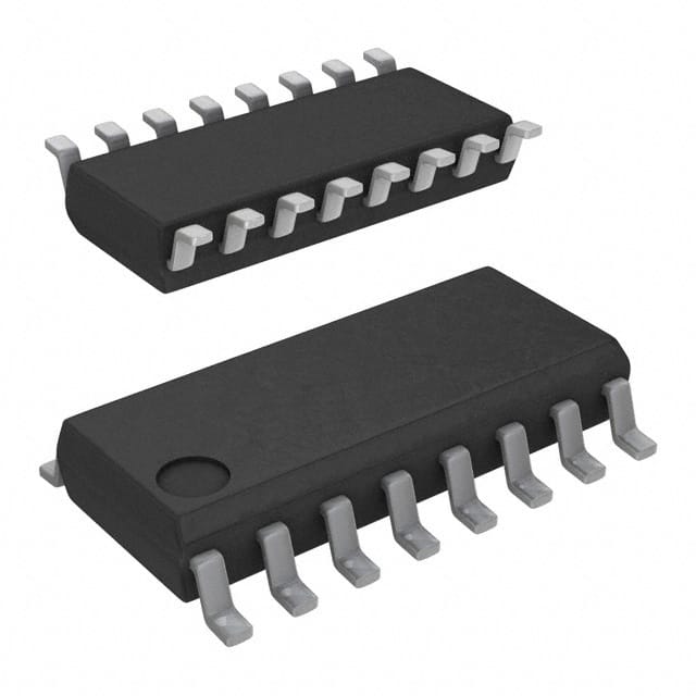
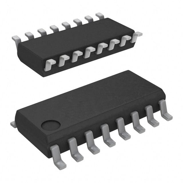
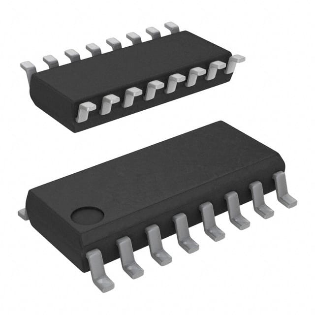
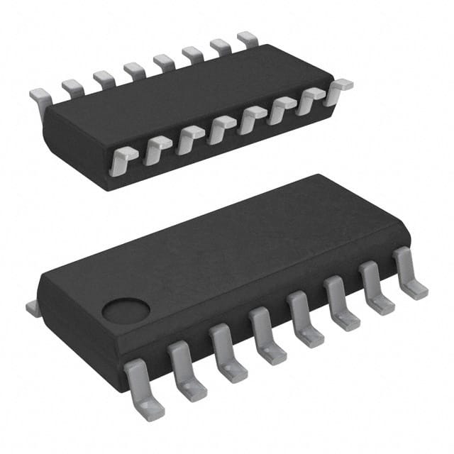
Clock Integrated Circuits (ICs) are vital components in timing electronic devices that regulate the timing and synchronization of various operations within a system. They generate precise timing signals necessary for the proper functioning of digital circuits. Clock ICs come in various types, each serving specific purposes in electronic systems.

What A Clock IC is?
Clock ic also known as Real Time Clock/Calendar or short for RTC, which is the use of phase locking technology (PLL) to generate clock signals. It can control the time between different components to ensure normal digital circuit operation. The crystal oscillator is a passive component based on electrical characteristics, which uses the mode of crystal oscillation to generate stable oscillating signals.The principle of clock integrated chip mainly includes the generation, frequency division, distribution and synchronization control of clock signal. Firstly, the generation of clock signal is one of the basic functions of clock circuit. Inside the chip, an oscillator or crystal is usually used to produce a stable clock signal. The frequency and stability of the clock signal are crucial to the working effect of the entire chip, so the generation of the clock signal must ensure its stability and accuracy. Secondly, the clock signal often needs to be divided frequency processing to meet the needs of different functional modules on the clock frequency. The frequency division circuit can divide the high frequency clock signal into multiple clock signals of the same or different frequencies to meet the working requirements of different functional modules. The design of the frequency division circuit needs to consider the phase and frequency stability of the clock signal to ensure that the clock signal can still meet the working requirements of the whole chip after the frequency division.

In addition, the clock signal also needs to be distributed and synchronized to ensure that each functional module can work in accordance with a unified timing. The distribution circuit can distribute the generated clock signal to each functional module, while the synchronous control circuit can ensure that each functional module works in accordance with the correct timing under the control of the clock signal, so as to avoid conflicts and errors between functional modules caused by inconsistent timing.
Why need clock signal in a timing IC?
The clock signal plays a very important role in the chip. It can be said that is the "heart" of the chip, equivalent to the heart of the human body, used to synchronize and control the operation between the various functional modules in the chip. The clock signal can provide a stable time benchmark, allowing the entire chip to work in a coordinated manner. Clock IC is a chip specially used to generate and control clock signals. As the most basic and important part of the chip design, the clock chip has the following main functions:1. Generation of clock signal: The timing chip can generate a stable clock signal through the internal circuit structure. The clock signal of different frequency and duty cycle can be realized through the precise clock oscillator, frequency divider and other modules.
2.Distribution of clock signal: It can assign the generated clock signal to other chips or modules to synchronize their operations. Through the extraction and distribution of clock signals, the cooperative work between multiple chips or modules can be achieved.
3.Calibrate signal: The clock chip can be calibrated by receiving external clock signals to ensure the accuracy and stability of the generated clock signal. And the calibration is achieved by an automatic calibration circuit or an external input calibration signal.
4.Clock signal management: This kind of clock chip can provide rich clock signal management functions, such as frequency adjustment, duty cycle control, clock delay management, etc. With these management functions, different application requirements can be flexibly met.
In a word, clock ICs are essential for maintaining synchronization and timing accuracy in electronic systems. Without them, devices would struggle to perform tasks accurately and efficiently. From simple digital clocks to complex microprocessors, clock ICs are fundamental building blocks of modern electronics.
How Many Type of Clock ICs in the Industry?
According to different functions, clock/timing ICs can be divided into Oscillators, Buffers, Generators, Jitter Attenuation and real time RTC chips. When an electronic system is running, a fixed, lower frequency clock signal can be provided by the oscillator, and the clock generator can adjust the signal to the different frequency required by each chip and output it. If more clock signal channels of the same frequency are required, a clock buffer (also known as a clock driver) can be used to increase the number of output channels of the clock signal of that frequency.In some communication scenarios with strong anti-interference capability, high clock signal jitter requirement or large clock signal jitter due to remote transmission interference, you need to use the de-jitter chip to de-jitter the jitter clock signal and synchronize it with the upstream device to ensure that the device can process data stably, at high speed, and accurately, and ensure the clock synchronization of the entire network. From the point of view of chip function, the clock chip is also can be seen as a clock generator. Then we will introduce them as details.
Oscillator
The Oscillator is generally a quartz oscillator, which belongs to the device product and is divided into active oscillator (OSC, Oscillator, that is, crystal oscillator) and passive crystal (XTAL, that is, crystal resonator). Active crystal oscillator is actually composed of passive crystal and oscillating circuit IC. The performance of IC plays an important role in the stability of the output frequency of crystal oscillator. Therefore, the active crystal oscillator can output the oscillating signal after the power supply, and the passive crystal must add an additional circuit to oscillate. In some scenarios with low precision requirements, such as low-end consumer electronics and mobile devices, passive crystals are used to generate low-frequency signals, while in some scenarios with high precision requirements, such as high-end communication equipment, industrial networks, power equipment, instrumentation and other fields, crystal oscillators are required. The common input voltage of crystal oscillator is 1.8V to 5V, and the commonly used nominal frequency is between 1-200MHz, such as 8MHz, 12MHz, 24MHz, 125MHz and so on.
Buffers
The main function of the clock buffer chip is to generate multiple same clock frequency signals through frequency replication. Generally speaking, the clock buffer refers to the fan-out buffer based on non-phase-locked loop (PLL) technology, and the clock buffer with higher accuracy is called the zero-delay clock buffer. The zero delay buffer can make the delay between the frequency signals of multiple outputs zero, and the deviation is very low, so the cost is higher. Zero-delay buffers are generally used for applications that require synchronous clocks, such as FPGA, CPU, logic, and synchronous memory.
The clock buffer itself cannot generate a frequency source, and its reference clock can be provided by a clock chip such as a resonator (quartz crystal or MEMS resonator), a crystal oscillator, or a clock generator. For circuits that require multiple identical clock inputs, the use of a clock buffer can eliminate the need for multiple quartz crystals or crystal oscillators, reducing costs, saving board space, and solving the problem of time synchronization. In addition, clock oscillators usually cannot support all loads, and the driving capacity is limited, and different chips due to different processes, packaging forms and operating voltages, etc., have different requirements for the format, level and driving capacity of the clock signal, so in addition to clock signal replication, The main functions of the clock buffer also include clock signal format conversion and clock signal level conversion.
Generators
Because the frequency of the original clock signal generated by the clock oscillator is low, and the frequency generated by the clock oscillator after the factory is fixed, it is difficult to meet the working frequency requirements of various chips in electronic devices, so it is necessary to use the clock generator chip or the phase-locked loop PLL circuit integrated on the chip for frequency synthesis, so as to form a high-frequency clock signal required to meet the work of the chip.
The clock generator generally needs an additional crystal or oscillator as a reference, and its main function is to achieve frequency conversion, which can double or reduce the frequency of the reference source crystal or oscillator, thus producing 1 or multiple outputs. The Phase Locked Loop (PLL) is the core technology of the clock generator. The PLL uses the reference signal of the external input to control the frequency and phase of the oscillation signal inside the loop, and realizes the automatic tracking of the output signal frequency to the input signal frequency. When the frequency or phase of the reference clock changes, the PLL will detect this change and adjust the output frequency through an internal feedback system until the phase of the two is re-synchronized, also known as "phase locking".
Jitter Attenuation
The jitter of the clock signal will affect the accuracy of the data in the transmission process, resulting in incorrect coding of the raw data obtained by the processor. When the clock signal jitter is certain, the higher the rate of information processing, the more error codes are contained in the information, which affects the efficiency of the whole system and may even crash. Therefore, a low jitter clock signal is essential for high-speed data processing systems.
To shake the chip is to filter the jitter, and there must be a low-pass filter inside the chip. The de-jitter chip can be regarded as a clock generator chip with added de-jitter function.
Real-Time Clocks (RTCs)
RTCs are specialized clock ICs that keep track of the current time and date. They often include features such as calendar functions and battery backup to ensure uninterrupted operation, even during power outages.
Applications of Clock ICs
Clock ICs are used in a wide range of electronic devices and systems, including but not limited to:Microcontrollers
Digital Signal Processors (DSPs)
Computer and server systems
Automobile systems
Industrial control
Comsumer electronic products
Jinftry has became one of the most largest electronic components supplier in the market, we supplied components to all over the world since 2013. At Jinftry, you can enjoy the stable supply chain, genuine guarantee, one-time delivery, competitive price and after-sales service for all products. If you are finding a reliable supplier for your projects or electronic device, please send your message immediately and we can reply within 12 hours.
Previous Chapter:What is Audio Special Purpose ICs and its function?
Next Chapter:What are Data Acquisition ICs?

